Linear Feedback Shift Registers: Pseudo-Randomness From Four Flip-Flops
What an LFSR is, how tap choice sets its period, and a 4-bit register traced through every state of its maximal-length cycle — taps, seeds and the zero trap
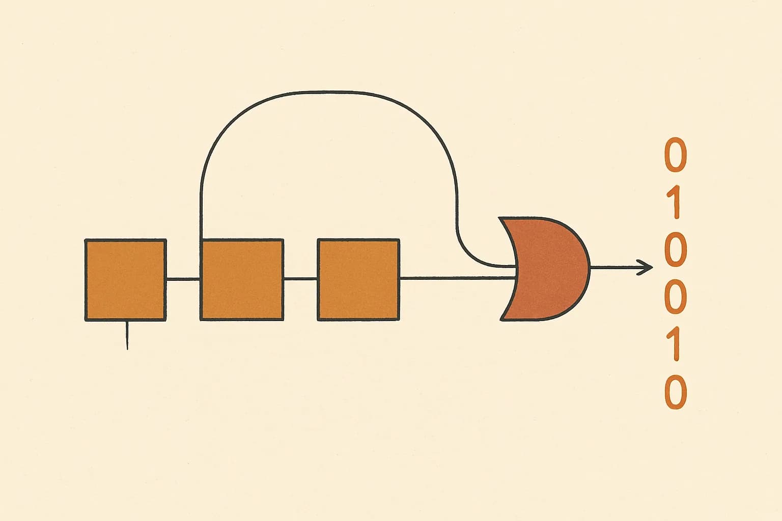
A linear feedback shift register — LFSR — is a row of memory bits that produces a long, random-looking bit sequence using almost no machinery. On every clock tick each bit slides one position toward the exit, and the single new bit that enters at the far end is the XOR of a fixed selection of the current bits. In hardware every cell of the row is one flip-flop, so a 4-bit LFSR is literally four flip-flops and an XOR gate. That poverty of parts is the entire appeal: for decades LFSRs have generated test patterns, scrambled data streams and supplied "noise" in chips where a real random source or a full pseudo-random algorithm would cost too much silicon.
The complete update rule fits in one line:
feedback = XOR of selected tap bits; shift right and insert feedback at the high bit
This is the Fibonacci form of the LFSR — all the selected bits feed one XOR, and its result becomes the new top bit. Everything people ask about LFSRs — which bits should feed back? why does the sequence repeat? why must the seed never be zero? — falls out of that line, and a 4-bit register is small enough to watch it happen state by state. That is exactly what the rest of this guide does.
Registers, taps and the tap mask
Three numbers define the machine. The width is how many bits the register holds; the examples here use 4. Bits are numbered from bit 0 at the low end — the bit that falls out on each shift — up to bit 3 at the high end, where the feedback comes in. The taps are the positions whose bits get XORed together, written compactly as a tap mask: mask 3 is binary 0011, which selects bits 0 and 1. The state (or seed, at the start) is whatever value the register currently holds.
One caution about conventions before any arithmetic: there is a second classical wiring, the Galois form, in which the feedback bit is XORed into several cells mid-register instead of feeding one gate at the input. It is a different calculation with different intermediate states, so an answer computed under one convention will not match a tool built on the other. Everything below uses the right-shift Fibonacci step quoted above, which is also the variant the linear feedback shift register calculator implements — one named rule, no blending.
One tick, traced in full
Start with the register holding 11, which is binary 1011, with tap mask 3 (bits 0 and 1) on a 4-bit register.
- Read the tapped bits: bit 0 of 1011 is 1, bit 1 is 1.
- XOR them: 1 XOR 1 = 0. That is the feedback bit.
- Shift right: 1011 becomes 0101 — the low 1 drops out the bottom.
- Insert the feedback at the high end: bit 3 becomes 0, leaving 0101, which is decimal 5.
So one tick maps 11 to 5 with a feedback bit of 0 — the same two outputs the calculator's own executable fixture reports for these inputs. Here are the first five ticks, each row computed the same way:
| State | Binary | Bit 1, bit 0 | Feedback (XOR) | Next state |
|---|---|---|---|---|
| 11 | 1011 | 1, 1 | 0 | 5 (0101) |
| 5 | 0101 | 0, 1 | 1 | 10 (1010) |
| 10 | 1010 | 1, 0 | 1 | 13 (1101) |
| 13 | 1101 | 0, 1 | 1 | 14 (1110) |
| 14 | 1110 | 1, 0 | 1 | 15 (1111) |
Fifteen states, then it repeats
Keep applying the step and the register tours every non-zero 4-bit value exactly once before returning home:
11 → 5 → 10 → 13 → 14 → 15 → 7 → 3 → 1 → 8 → 4 → 2 → 9 → 12 → 6 → back to 11.
That is a period of 15, and 15 is the theoretical ceiling. A 4-bit register has 2⁴ = 16 possible patterns, but all-zeros is a trap: every tapped bit is 0, so the feedback is 0, and shifting 0000 reproduces 0000 forever. The longest possible tour is therefore 16 − 1 = 15 states, and a tap set that achieves it is called maximal-length — mask 3 is one.
The usable output of an LFSR is usually the bit that falls off the low end each tick. Reading it across the full cycle above gives the stream 110101111000100 — 8 ones and 7 zeros (8 + 7 = 15). That near-perfect balance, off by exactly one because the all-zeros state is the one pattern never visited, is the first of the statistical properties that make maximal-length sequences useful as pseudo-noise.
Taps decide everything
Change nothing but the mask and the machine can collapse. Running every state by the same rule, from seed 1 (0001), a 4-bit register gives:
| Tap mask | Binary | Taps | Period from 0001 |
|---|---|---|---|
| 3 | 0011 | bits 0, 1 | 15 — maximal |
| 9 | 1001 | bits 0, 3 | 15 — maximal |
| 1 | 0001 | bit 0 | 4 |
| 5 | 0101 | bits 0, 2 | 6 |
| 15 | 1111 | bits 0–3 | 5 |
Checking all fifteen possible masks exhaustively, only 2 of 15 — masks 3 and 9 — are maximal at this width. The failures fail in instructive ways. Mask 1 feeds the departing bit straight back to the top, which is just a rotation: 0001 → 1000 → 0100 → 0010 and around again, period 4. Mask 5 wanders through 6 states; tapping everything (mask 15) manages only 5.
The worst mistake is a mask that skips bit 0 entirely, such as mask 12 (1100). Then the bit shifted out vanishes without ever influencing the feedback, so information is destroyed: states 0000 and 0001 both step to 0000. Once two states share a successor the update is not invertible, the state diagram grows dead-end branches, and the register can slide into the zero trap it was supposed to avoid. A working tap set must include the exit bit.
And whatever the mask, seeding with zero parks the machine permanently — which is why the tool's register input starts at 1, not 0.
Wider registers, longer cycles
The ceiling scales as 2ⁿ − 1. A 2-bit register can visit at most 2² − 1 = 3 states; 8 bits allow 2⁸ − 1 = 255; 16 bits allow 2¹⁶ − 1 = 65,535 — matching the 2-to-16-bit widths and 65,535 maximum register value the calculator accepts. But as the 4-bit enumeration showed, most masks fall far short of the ceiling, and the fraction that reach it must be found width by width. Serious designs pick taps from published maximal-length tables rather than guessing.
Pseudo-random, with the emphasis on pseudo
A maximal LFSR passes casual randomness checks while being perfectly deterministic. The next state is a fixed function of the current one, so anyone who knows the taps and observes the register once can run the rule forward and predict every future bit — with 4 bits of state, the whole future above followed from the single value 11. The feedback is also purely linear (XOR only), which makes the sequence easy to reconstruct from a short stretch of output. That is fine, even ideal, for test stimulus, scrambling where the receiver shares the taps, and evenly-covering counters. It is disqualifying for anything secret: an LFSR on its own is never a cryptographic generator.
Step through your own register
The fastest way to internalize all of this is to run a register of your own. The LFSR step calculator performs exactly one audited right-shift step on a 2-to-16-bit unsigned register and shows both the next state and the feedback bit; polynomial notation, maximal-period selection and sequence generation are deliberately outside its scope. Feed each result back in as the new register value and you rebuild cycles like the fifteen-state tour above by hand — the arithmetic never hides. It is intentionally one of the narrowest tools on Quanta, because a step you can verify beats a sequence you have to trust. When that narrowness eventually gets in the way of something you are building, the contact page is the place to say so. Until then: seed 11, mask 3, and fourteen more states to check by hand.
Sources
- AMD (Xilinx) Application Note XAPP052 — efficient shift registers, LFSR counters, and long pseudo-random sequence generators, with maximal-length tap tables
- ITU-T Recommendation O.150 — pseudo-random bit sequences (PRBS) generated by shift registers for digital test equipment
- IETF RFC 4086 — randomness requirements for security, and why linear generators are not enough