MOSFET Threshold Voltage: What V-th Actually Marks
What a MOSFET's threshold voltage marks, the test-current convention datasheets use to measure it, and how body bias and temperature move the real number
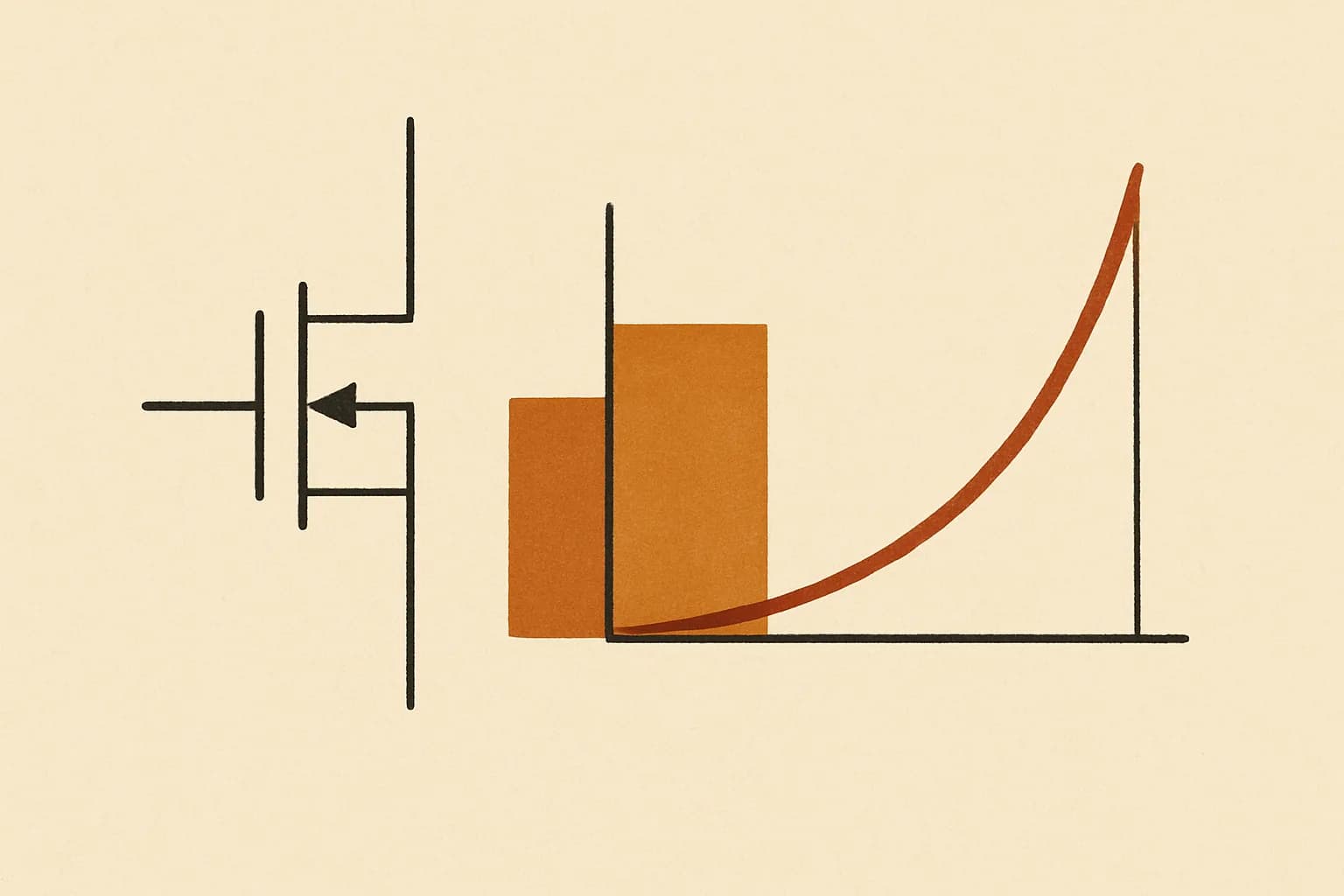
Threshold voltage — V_th on a forum, V_T in a textbook, V_GS(th) on a datasheet, VTO in a SPICE model card — is the gate-to-source voltage at which a MOSFET's channel forms and the device starts to conduct. Below it the transistor blocks; above it, drain current climbs with the square of the gate drive beyond it. That is what V_th marks: the boundary between cutoff and conduction — the entry fee, in gate voltage, paid before the transistor does anything.
The catch is that the threshold is not a single number, even for one physical transistor. The figure a datasheet prints is measured under two conventions — source tied to the body, and "conducting" defined as a small stated test current — and real circuits break both. Raise the source above the substrate and the threshold climbs; warm the die and it falls; compare two documents that chose different test currents and they disagree about the same silicon. What follows unpacks each convention and ends with a table of the ways a measured threshold escapes the printed one.
Four symbols, three different numbers
| Symbol | Where it appears | What it denotes |
|---|---|---|
| V_GS(th) | Datasheets | Gate-source voltage producing a stated test drain current |
| VTO (V_T0) | SPICE model cards | Threshold with the source tied to the body, V_SB = 0 |
| V_T | Circuit analysis | Threshold at your actual bias point, body effect included |
| V_th | Informal usage | Any of the above — context decides |
These are genuinely different quantities: VTO is a device parameter, V_T is what it becomes inside your circuit, and V_GS(th) is what a production tester can verify in milliseconds. (For enhancement-mode n-channel parts all three are positive; depletion-mode devices carry negative thresholds and conduct until the gate is pulled below the source.) Asked what V_th "means", the honest first answer is: which of the three is your document quoting?
The measurement convention: a test current, not a magic moment
Physically, the threshold is the gate voltage at which an inversion layer — a thin sheet of electrons pulled up under the gate oxide — forms and connects source to drain. The square-law model calls the current exactly zero below threshold, but real silicon turns on gradually, and "the moment the channel forms" is nothing a production tester can observe. Datasheets settle it by decree: V_GS(th) is the gate voltage at which the drain passes a stated current, often 250 µA. Two manufacturers choosing different test currents will print different thresholds for comparable devices — neither wrong, just differently calibrated.
Temperature moves the goalposts too: threshold falls roughly 2 mV per °C of die temperature, so a device running 50 °C above the bench where you probed it sits about 2 × 50 = 100 mV lower — a hot MOSFET turns on more easily, not less.
The body effect: where the datasheet stops being enough
The largest and least-advertised shift has nothing to do with how the number was measured. The datasheet assumes the source sits at the body (substrate) potential. Whenever the source instead sits above the body — a transistor stacked on another, a source follower, almost any device in an IC whose substrate ties to the most negative rail — the source-body junction is reverse biased, the depletion region under the channel widens, and more gate charge is needed before inversion. Georgia Tech's ECE 3050 notes and MIT OpenCourseWare's 6.720J notes write it in different sign conventions but agree on the resulting threshold:
V_T = V_T0 + γ(√(2Φ_F + V_SB) − √(2Φ_F))
Here γ is the body-effect coefficient (SPICE's GAMMA), fixed by substrate doping and oxide thickness as √(2qN_Aε_S)/C_ox; 2Φ_F is the surface potential (SPICE's PHI), close to 0.6 V for silicon; and V_SB is how far the source sits above the body.
Run it once with the example device from the MOSFET threshold voltage calculator: V_T0 = 0.7 V, γ = 0.5 √V, 2Φ_F = 0.6 V, and one volt of source-body bias. The square roots are √1.6 = 1.264911 and √0.6 = 0.774597; their difference is 0.490314, and multiplying by γ gives a shift of 0.5 × 0.490314 = 0.245157 V. The working threshold is 0.7 + 0.245157 = 0.945157 V. That is 0.245157 ÷ 0.7 = 0.35 — a 35 % increase over the nameplate figure, from a single volt of bias no datasheet page mentions.
The second volt is cheaper than the first
Because the shift rides a square root, it decelerates. Push V_SB to 2 V: √2.6 = 1.612452, minus 0.774597 leaves 0.837855, times γ gives 0.418927 V of total shift and a threshold of 0.7 + 0.418927 = 1.118927 V. The second volt therefore cost 0.418927 − 0.245157 = 0.173770 V — about 174 mV against the first volt's 245 mV.
The instantaneous rate has its own symbol: χ = γ ÷ (2√(2Φ_F + V_SB)), which at V_SB = 1 V evaluates to 0.5 ÷ (2 × 1.264911) = 0.5 ÷ 2.529822 = 0.197642 — call it 198 mV of threshold per further volt of body bias. The University of Toronto lecture notes the calculator cites put typical values between 0.1 and 0.3. χ also equals g_mb/g_m — how strongly the substrate acts as an unwanted second gate, and the quantity behind a source follower's below-unity gain.
Why a small threshold error becomes a large current error
Threshold errors do not stay their own size, because saturation current follows a square law: I_D = K(V_GS − V_T)², valid while V_DS is at least the overdrive V_GS − V_T. The overdrive doubles as V_DS(sat), the edge of saturation, and is the quantity an operating point is built from — the discipline a BJT stage gets from the transistor biasing calculator.
Drive the example device with V_GS = 3 V. Against the true threshold the overdrive is 3 − 0.945157 = 2.054843 V, and with K = 1 mA/V² the current is 2.054843² = 4.2224 mA. Ignore the body effect and you would predict an overdrive of 3 − 0.7 = 2.3 V and a current of 2.3² = 5.29 mA. The overdrive error is (2.3 − 2.054843) ÷ 2.054843 = 12 %, but squaring inflates it: (5.29 − 4.2224) ÷ 4.2224 = 25 % too much predicted current.
Conventions disagree here too, this time between textbooks. The form above, with K = ½µC_ox(W/L), is the one in the Georgia Tech notes; other texts write I_D = (K/2)(V_GS − V_T)², making their K exactly twice this one. Mix them silently and every current you compute is off by a factor of two — the notes flag the trap explicitly, and the calculator states its definition of K next to the input for the same reason.
When there is no body effect at all
Every discrete MOSFET — the TO-220 on your bench included — has its body bonded to its source inside the package. V_SB is structurally zero, the shift term vanishes, and the datasheet threshold is the operative number. That internal bond is why the schematic symbol shows a diode between source and drain: the body diode, a p-n junction whose exponential current-voltage behaviour belongs to the Shockley diode equation calculator — and why the threshold tool rejects negative V_SB, since pulling the source below the body forward-biases that junction and, on an IC, risks latch-up.
The body effect is, in short, an integrated-circuit problem: one substrate serves every transistor on the die and ties to one rail, so any device whose source floats above that rail pays the surcharge computed above.
Why datasheets — and your bench — disagree
| Source of disagreement | Direction | Scale in the worked example |
|---|---|---|
| Test-current convention | Either way | "On" defined at a stated current, often 250 µA |
| Die temperature | Down as it warms | ≈ 2 mV/°C, so 100 mV across a 50 °C rise |
| Body effect (V_SB > 0) | Up, always | 245 mV at V_SB = 1 V; 419 mV at 2 V |
| VTO quoted as V_T | — | 0.7 V and 0.945 V are both "the threshold" |
| K convention (hits current, not V_th) | Factor of 2 in I_D | 4.22 mA misread as 8.44 or 2.11 |
A MOSFET that refuses to turn on where its datasheet promised is almost always one row of this table, and the quickest diagnosis is to stop trusting defaults: put your own device's VTO, GAMMA and PHI into the threshold calculator and compare its answer with what your bench measures. Like every tool on Quanta, it prints the equations it implements and where they came from, so any disagreement narrows to your parameters or your probe setup — and on the rare occasion neither is at fault, the contact page reaches the people who maintain the table above. Most such mysteries, though, dissolve the moment V_SB stops being assumed zero.