Scale Drawings: Reading 1:50 Plans Like a Builder
What 1:50 means in centimetres, how to convert drawing lengths in both directions, and the resizing, unit and area traps that misread floor plans
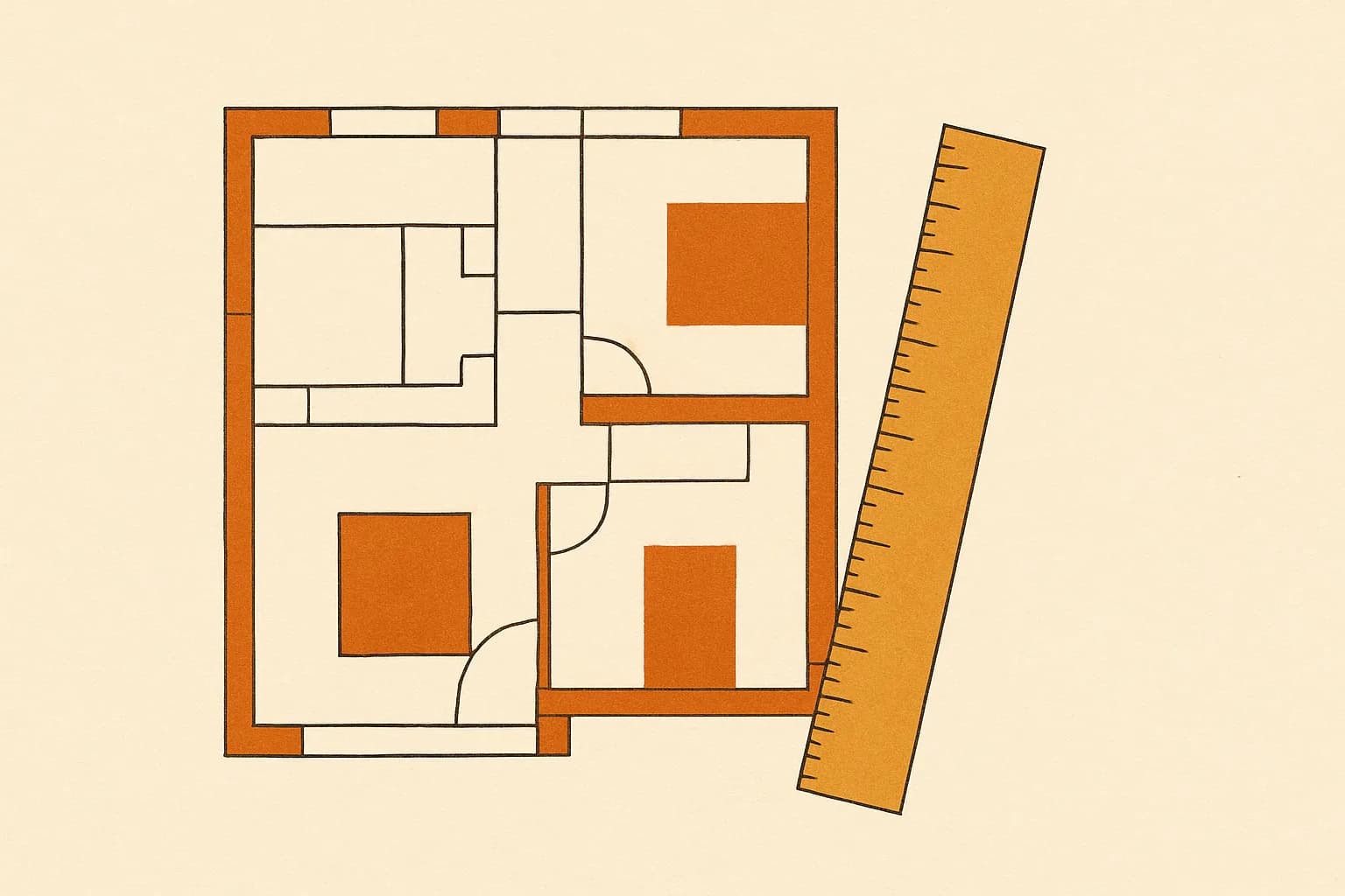
Type "1 50 scale in cm" into a search bar and here is the complete answer: on a 1:50 drawing, every 1 cm on paper stands for 50 cm — half a metre — in the real building. A wall that measures 2.5 cm on a 1:50 floor plan is therefore 2.5 × 50 = 125 cm long, which is 1.25 m. The ratio itself carries no unit, and that is precisely what makes it portable: 1 mm on the same sheet represents 50 mm, and 1 inch represents 50 inches. The U.S. Geological Survey calls this notation a representative fraction, and its single governing rule is that both sides of the ratio use the same unit.
That one relationship answers every question a scale drawing can pose, but it gets used in three different directions, and confusing the directions — or the units — is how plans get misread on site. This guide works all three directions with visible arithmetic, then covers the two traps that catch even experienced readers: sheets that have been silently resized, and areas, which do not scale the way lengths do. The scale conversion calculator automates each direction, but every step below can be checked by hand.
One formula, three directions
The calculator implements the representative-fraction definition directly. For a scale written A:B, where A units of drawing equal B units of reality:
actual length = drawing length × scale denominator ÷ scale numerator
On an ordinary reduction scale the numerator is 1, so the rule collapses to something a site foreman can say out loud: multiply by the big number going from paper to world, divide by it going back.
| You know | You want | Operation | On a 1:50 plan |
|---|---|---|---|
| Drawing length and the scale | Actual length | Multiply by 50 | 2.5 cm × 50 = 125 cm |
| Actual length and the scale | Drawing length | Divide by 50 | a 3 m (300 cm) door → 300 ÷ 50 = 6 cm |
| Both lengths, scale unknown | The scale | Actual ÷ drawing | 300 ÷ 6 = 50, written 1:50 |
The third row is the underrated one. When a title block is missing, illegible, or untrustworthy, a single known dimension recovers the scale: find a length written on the plan, measure that same line on the paper in the same unit, and divide actual by drawing. The calculator's find-scale mode normalises the result to 1:N so it can be compared against standard notation.
The builder's first move: verify the sheet
Nobody experienced scales a length off a drawing before checking the sheet itself, because printing with "fit to page," photocopying, scanning, and viewing a PDF at an arbitrary zoom all resize the geometry without updating the title block. The stated scale describes the original document, not necessarily the copy in your hand.
The check costs thirty seconds. Pick a dimension line that carries a written figure — say 3,600 mm on a plan stamped 1:50 — and measure it with a ruler. It should span 3,600 ÷ 50 = 72 mm on the paper. If it measures anything else, the sheet is not at its stated scale: treat it as not-to-scale and work only from the written dimensions, which always govern over anything you measure. This is also why a scale bar printed on the sheet beats a ratio in the title block — the bar resizes along with the drawing, so it stays honest even when the notation lies.
What 1 cm represents at the common scales
Scale designations sound arbitrary until each is translated into a sentence. The middle column below is simply 1 cm × N; the right-hand column expresses the drawing as a percentage of full size, 1 ÷ N × 100 — at 1:50 that is 1 ÷ 50 × 100 = 2%.
| Scale | 1 cm on paper represents | Drawing as % of full size | Typical territory |
|---|---|---|---|
| 1:20 | 20 cm (0.2 m) | 5% | construction details, joinery |
| 1:50 | 50 cm (0.5 m) | 2% | room and floor plans |
| 1:100 | 100 cm (1 m) | 1% | whole-building plans, elevations |
| 1:200 | 200 cm (2 m) | 0.5% | site layouts |
ISO 5455, the international standard for technical-drawing scales, groups all of these as reduction scales and also recognises full size (1:1) and enlargement scales, where the pattern flips: at 5:1, a five-centimetre drawing represents a one-centimetre object, making the drawing 500% of actual size — the convention for small mechanical details.
American residential sheets often state the scale differently — "¼ inch = 1 foot" — but it converts to the same notation. A foot is 12 inches, so 12 ÷ 0.25 = 48, and quarter-inch scale is 1:48. That makes it a near-neighbour of 1:50: the two differ by a factor of 50 ÷ 48 ≈ 1.04, about 4% — close enough that the drawings look identical, far enough to wreck a cut list if you convert with the wrong one. The A/E/C Graphics Standard published by the U.S. Army Corps of Engineers catalogues these drawing-scale conventions for U.S. construction documents.
The hundred-fold unit error
The same-unit rule sounds pedantic until you watch it fail. Suppose a plan note says a wall is 3 m long, and the wall measures 6 cm on the sheet — what is the scale? The correct move is to convert first: 3 m is 300 cm, and 300 ÷ 6 = 50, so the plan is at 1:50. Divide the raw numbers instead — 3 ÷ 6 = 0.5 — and you get 1:0.5, which claims the drawing is double real size. The answer is wrong by a factor of exactly 100, because that is the centimetres-per-metre conversion that was skipped. Any unit pair works the same way: keep both lengths in centimetres, or both in metres, or both in inches, and only convert to something friendlier after the division.
Areas scale by the square, not the ratio
Lengths scale by N; areas scale by N². This is the trap hiding in every "how big is this room?" question.
Take a room drawn 8 cm × 6 cm on a 1:50 plan. Convert each side first: 8 × 50 = 400 cm = 4 m, and 6 × 50 = 300 cm = 3 m, so the real room is 4 × 3 = 12 m². Now compare against the paper: the drawn rectangle covers 8 × 6 = 48 cm², and 12 m² is 12 × 10,000 = 120,000 cm². The ratio of real area to paper area is 120,000 ÷ 48 = 2,500 — which is 50², not 50. Multiply a paper area by the bare ratio and the answer comes out fifty times too small. The safe habit is mechanical: convert every length to real-world units first, and only then do area arithmetic.
Once the lengths are real, area questions belong to an area tool rather than a scale tool. On an American plan at quarter-inch scale (1:48), a room drawn 5 in × 4 in converts to 5 × 48 = 240 in = 20 ft and 4 × 48 = 192 in = 16 ft. Feed those real dimensions into the square footage calculator and it returns 20 × 16 = 320 sq ft — with the metric equivalent computed as 320 × 0.09290304 = 29.7289728 m², using the exact NIST conversion factor that follows from the foot being defined as exactly 0.3048 m. Its L-shape mode handles the room-plus-alcove floor plans that a single rectangle can't. The one discipline to keep: the calculator wants world dimensions, never paper ones.
The reading order that avoids all of it
Put together, reading a plan like a builder is a fixed sequence rather than a talent. Verify the sheet against one written dimension before trusting any measurement. Keep every pair of lengths in a single unit until after the division or multiplication. Multiply by the denominator from paper to world, divide going back, and square the factor the moment area enters the picture. When the scale itself is the unknown, one honest dimension and one ruler measurement recover it.
The scale conversion calculator runs all three directions and reports the scale factor and percentage as cross-checks, and the rest of the supporting arithmetic — unit conversions, ratios, areas — lives one search away on Quanta. What the tools don't yet read are the older notations: an engineer's chain scale, a pre-metric imperial sheet. If that is what's pinned to your site table, describe the drawing to us and it joins the build queue.